A new update of my network home setup, to both hardware and software.
Introduction
In this new “update/release” I have added two 120mm fans inside the server cabinet, I switched to Wi-Fi AX/6, I configured my network with separated VLANSs (IoT, Guest and Main), I connected both the computer and the television with an ethernet cable and I made some little modifications to the Grafana and Prometheus setup.
Before the beginning, I have to remember the “previous versions”, just in case you’re interested in all the steps that led me here:
- Jan 14, 2022 - My hardware and software setup for a new house
- Jun 02, 2022 - My network home setup - v2.0
- Aug 14, 2022 - My network home setup - v3.0
- Dec 12, 2022 - Some custom push notifications that improved my life
- Dec 19, 2022 - Retrieve a scheduled report of your Grafana dashboards via mail
- Now - My network home setup - v4.0
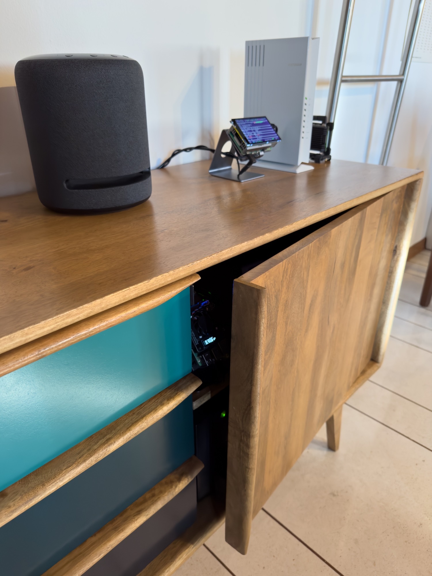
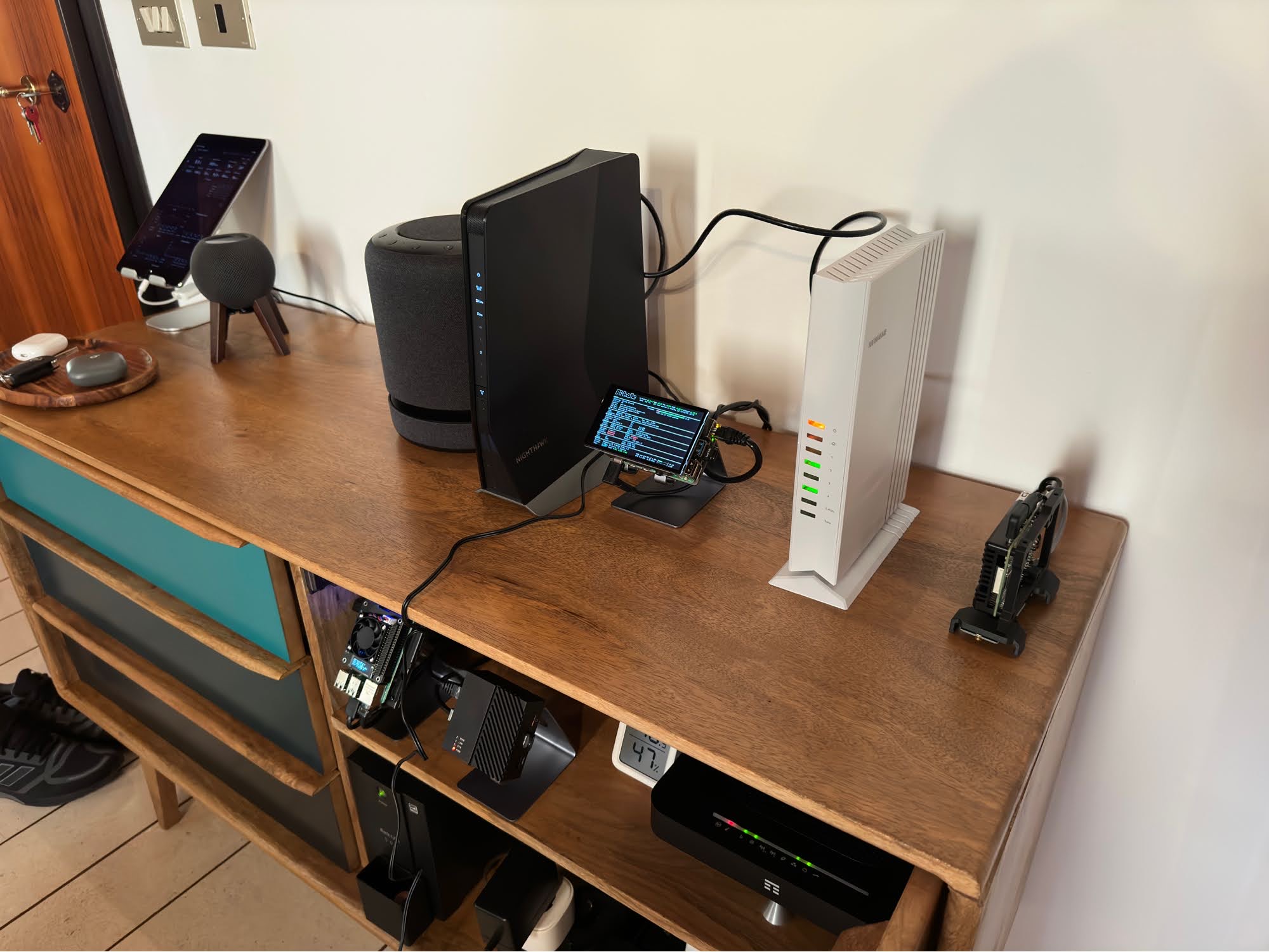
As always, before the details, the final result:
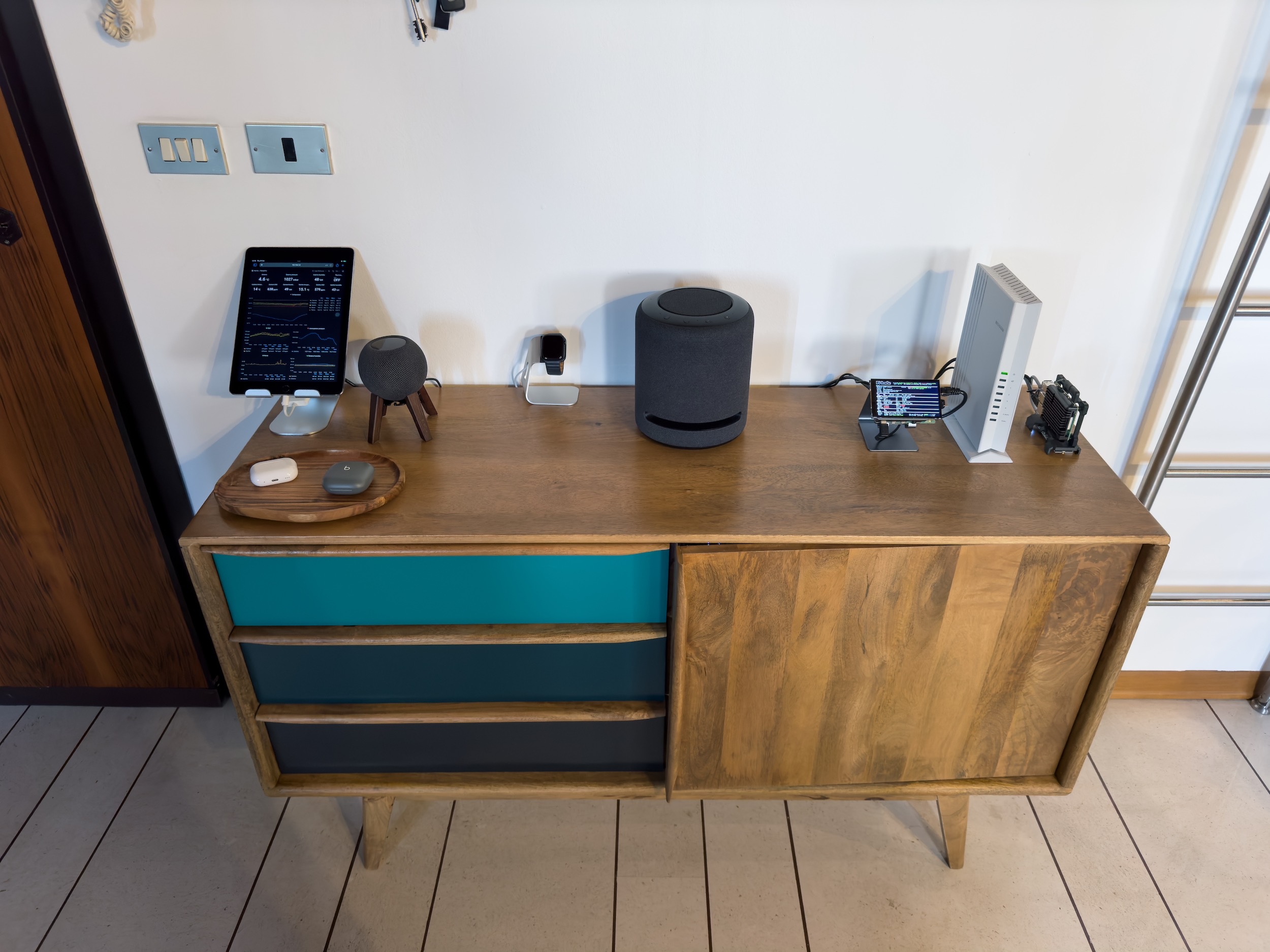
Hardware
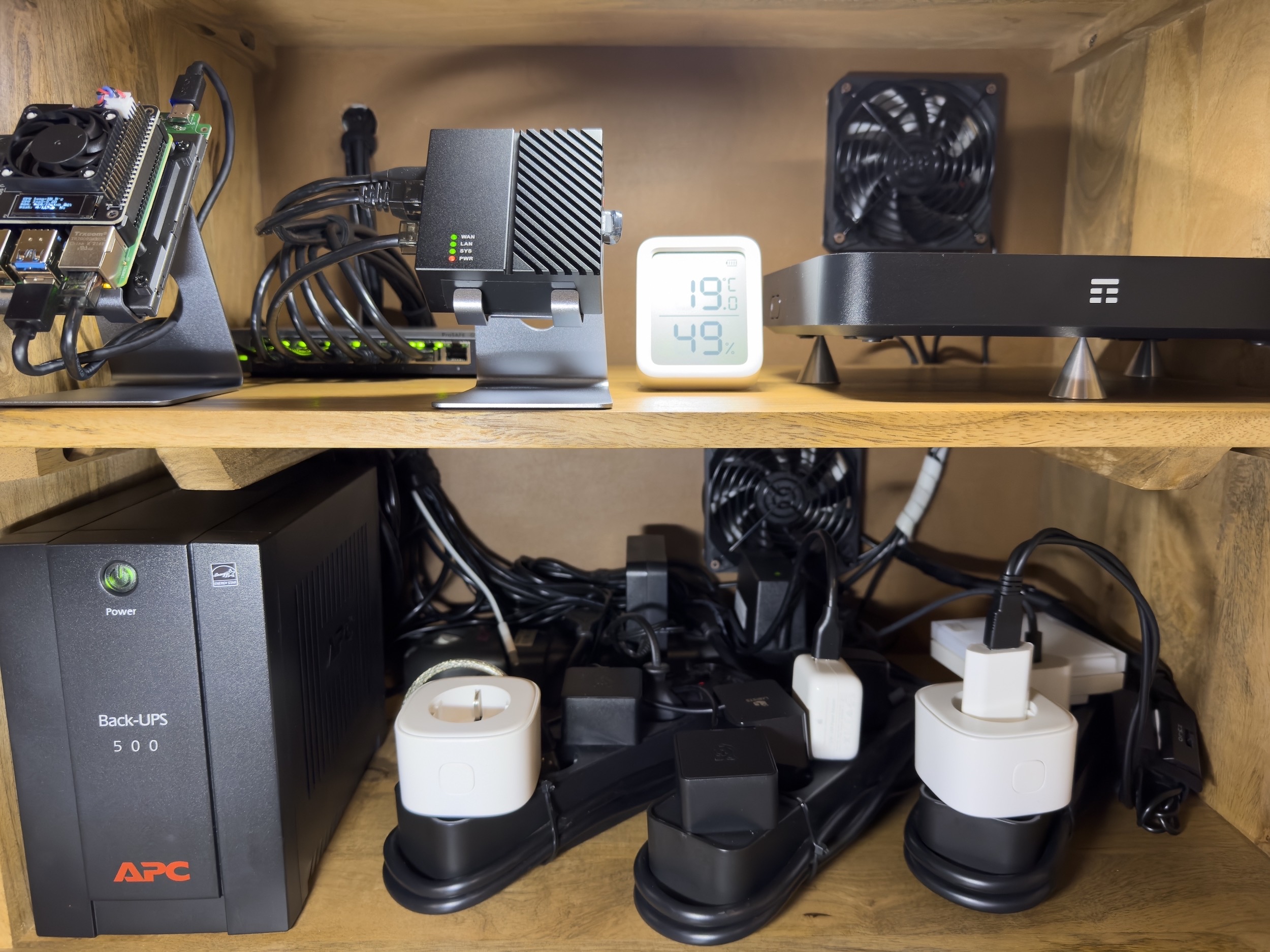
Starting with the hardware, the first new thing is a DIY modification to my server cabinet.
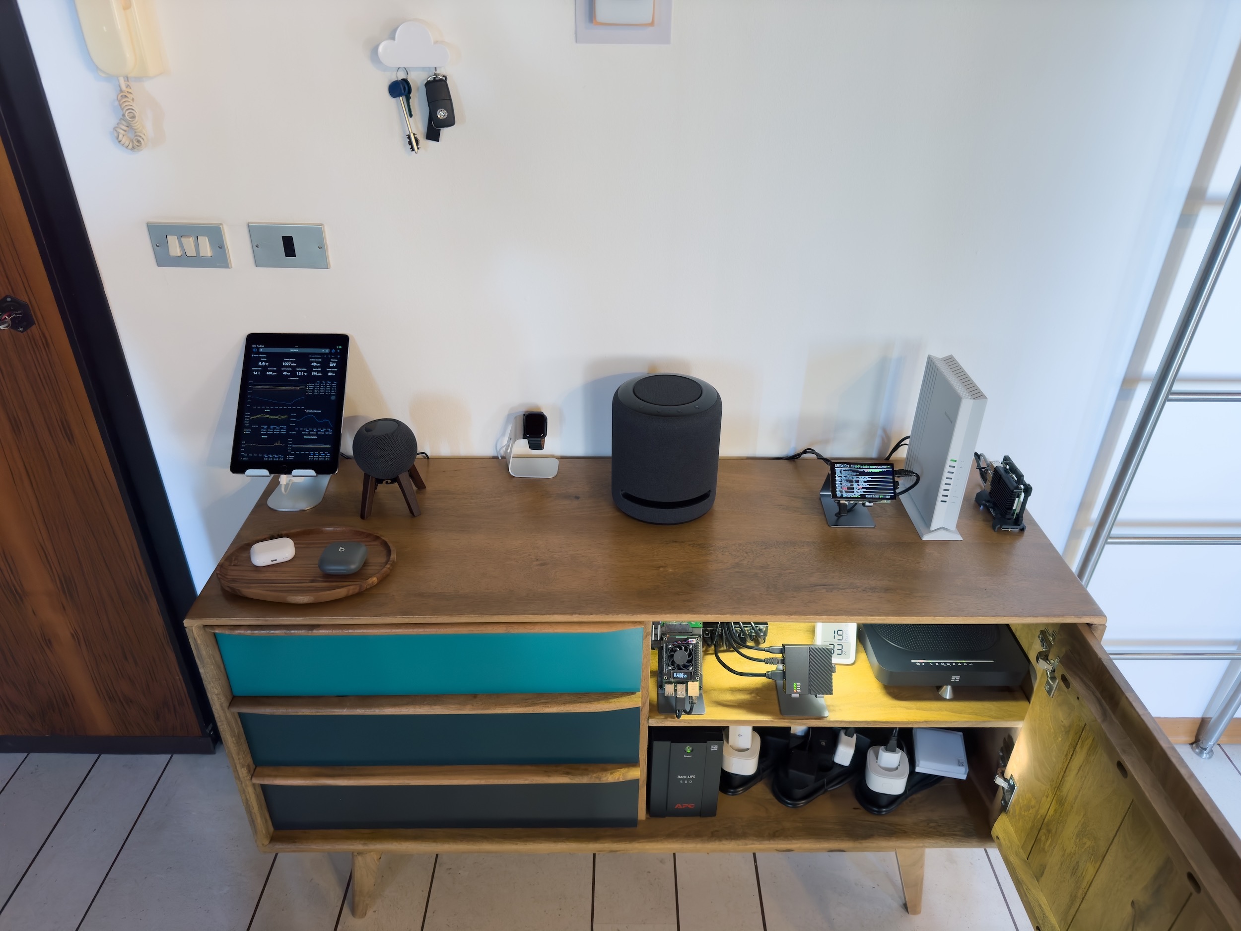
Breeze for the hardware
My server cabinet…is not a server cabinet, but is a wooden furniture from Maisons du Monde: Janeiro), it works fine as a cabinet because I bought it for this purpose, and it is also nicer and well integrated inside a home, than a metal cabinet/rack.
The only downside are the (high) temperatures during the summer, when the door is closed. So I had to lower the temperatures, for this reason I decided to install two 120mm fans inside the cabinet that extract the hot air from the inside. Also they are connected to a smart plug so I can use a simple automation to start them only when the temperature inside the cabinet is above x ºC (I think 28/30°) and they shut down automatically when the temperature is below x °C (I think 24°), I will tune the temperature the next summer.
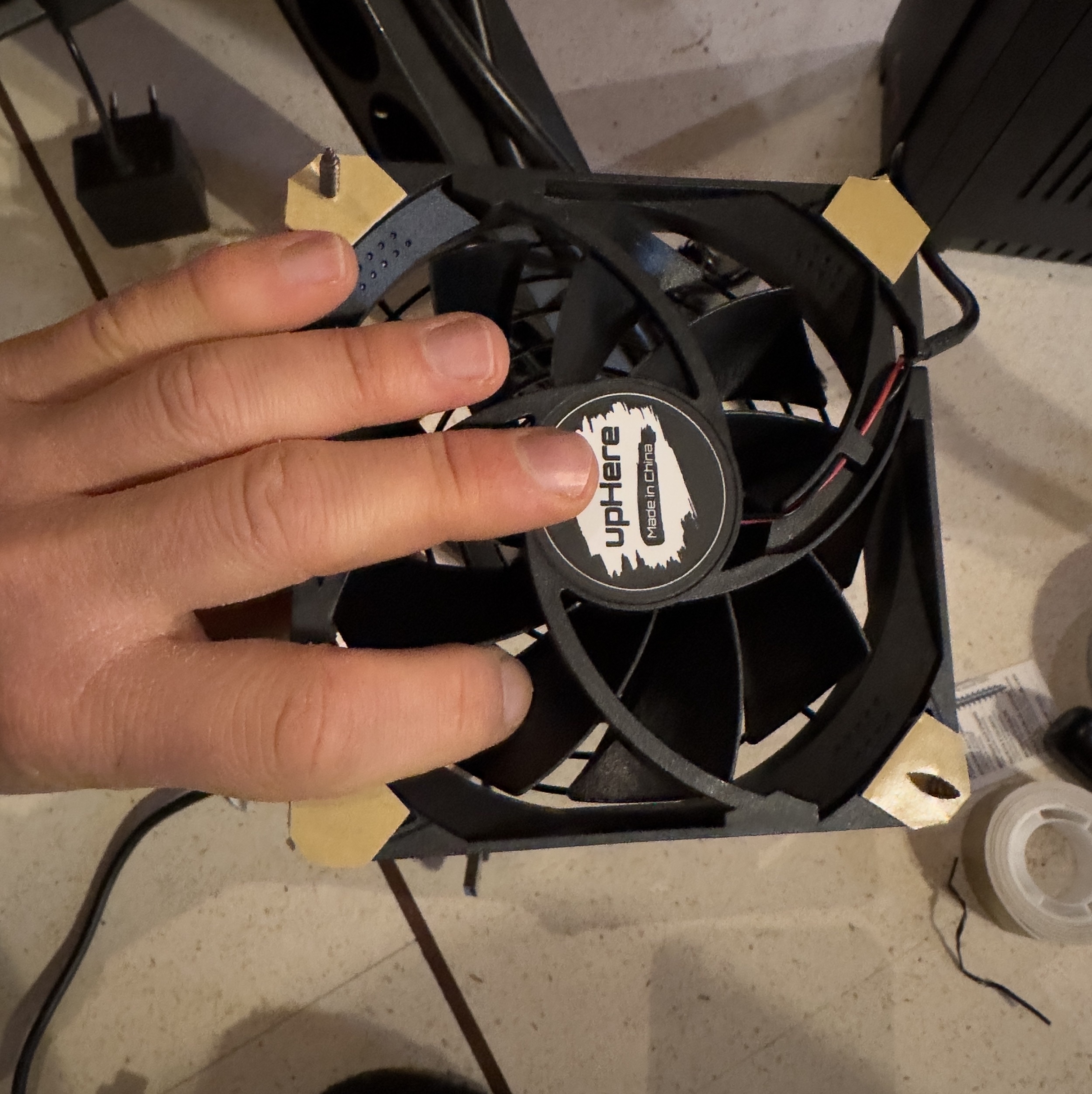
I know that 120mm could sound like big fans, and they are big, but since I want to have a low noise , I bought them with 3 speeds and I’ll use them at the lowest speed. This because the bigger are the fans, the more air they can move by spinning at a low rpm/rotation.
I choose a set of two USB fans for 17€ on Amazon, with 3 speeds, long cables and front grill (to avoid that a cable can enter inside): link.
I also decided that they have to extract hot air, and not blow fresh air inside, because above the cabinet I have an air conditioner, so I can leave the cabinet door with a little slot and the fans can create an airflow with cold air blow inside from the front, that is extracted from the rear of the cabinet.
Last, I bought the correct tool to make a 120mm circle hole: (link).
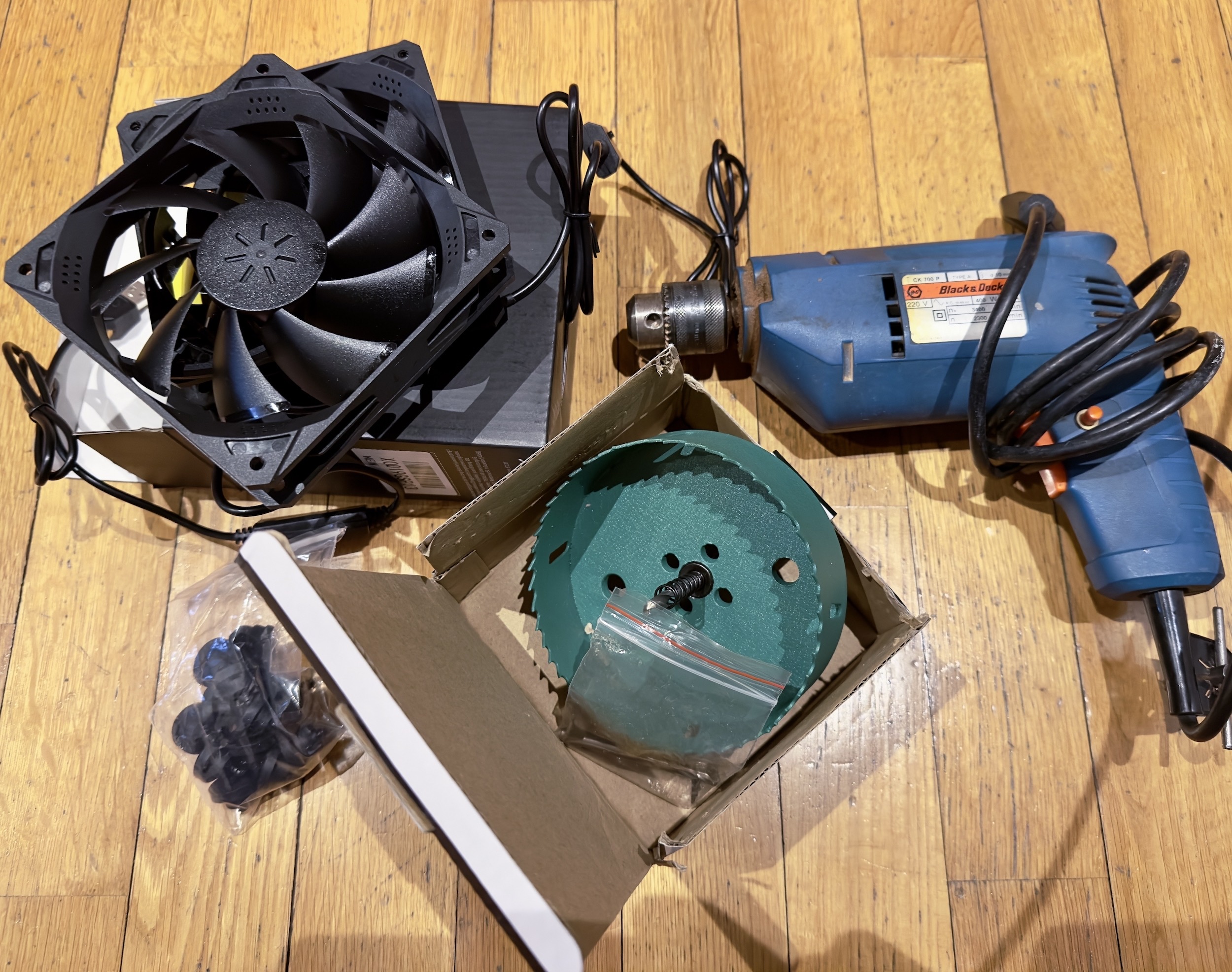
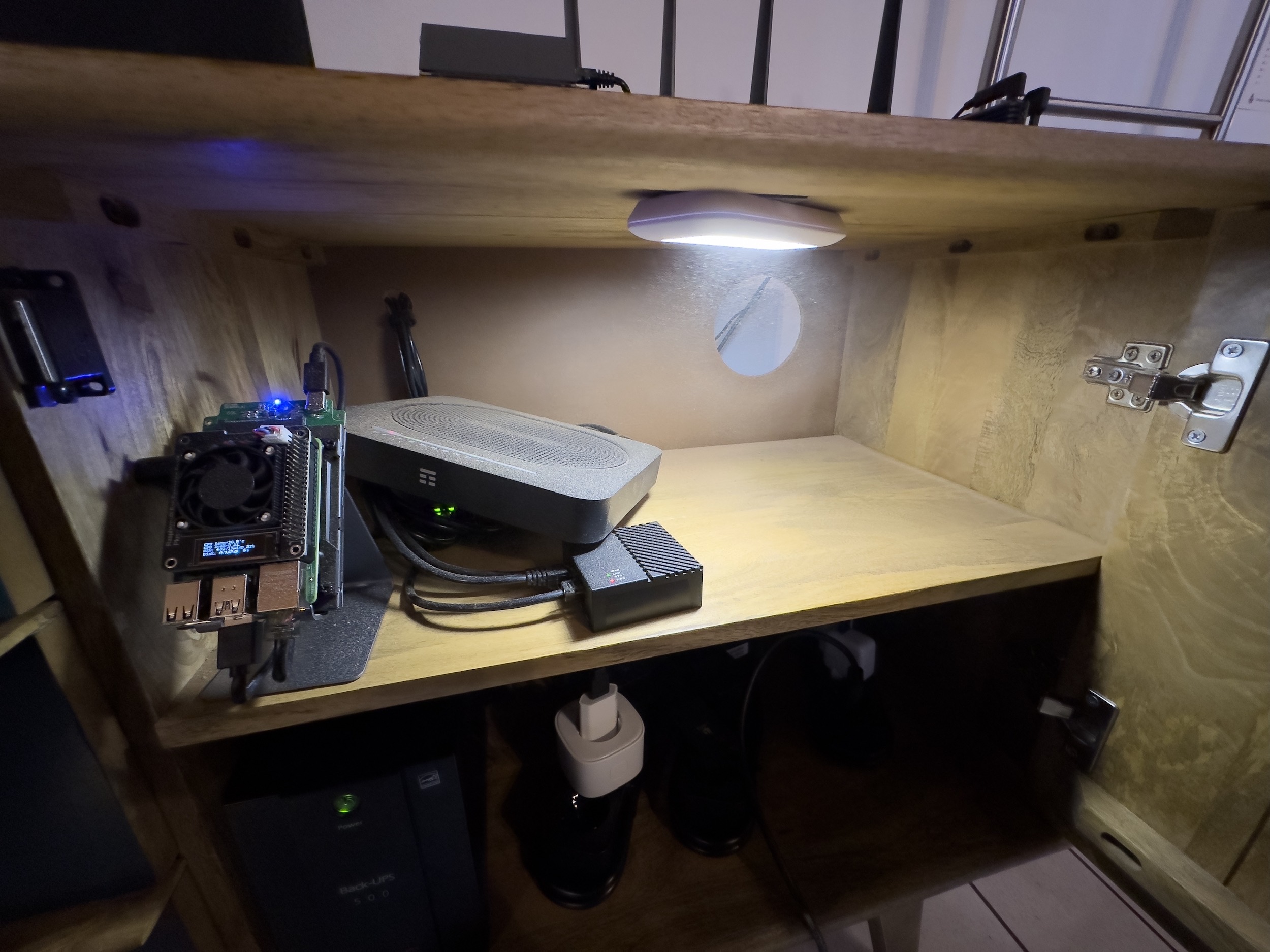
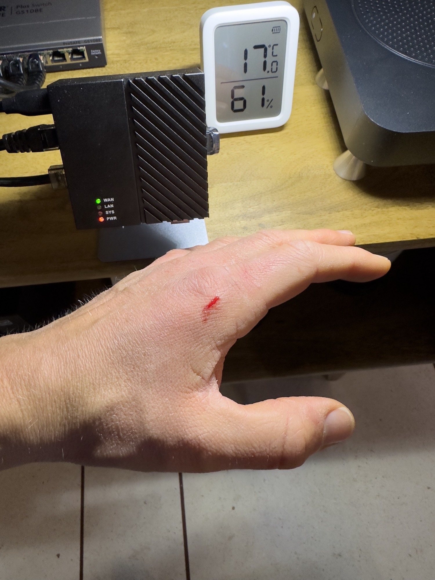
I simply removed some inside hardware and I drilled the holes, very easy (the after work cleanup was not easy).
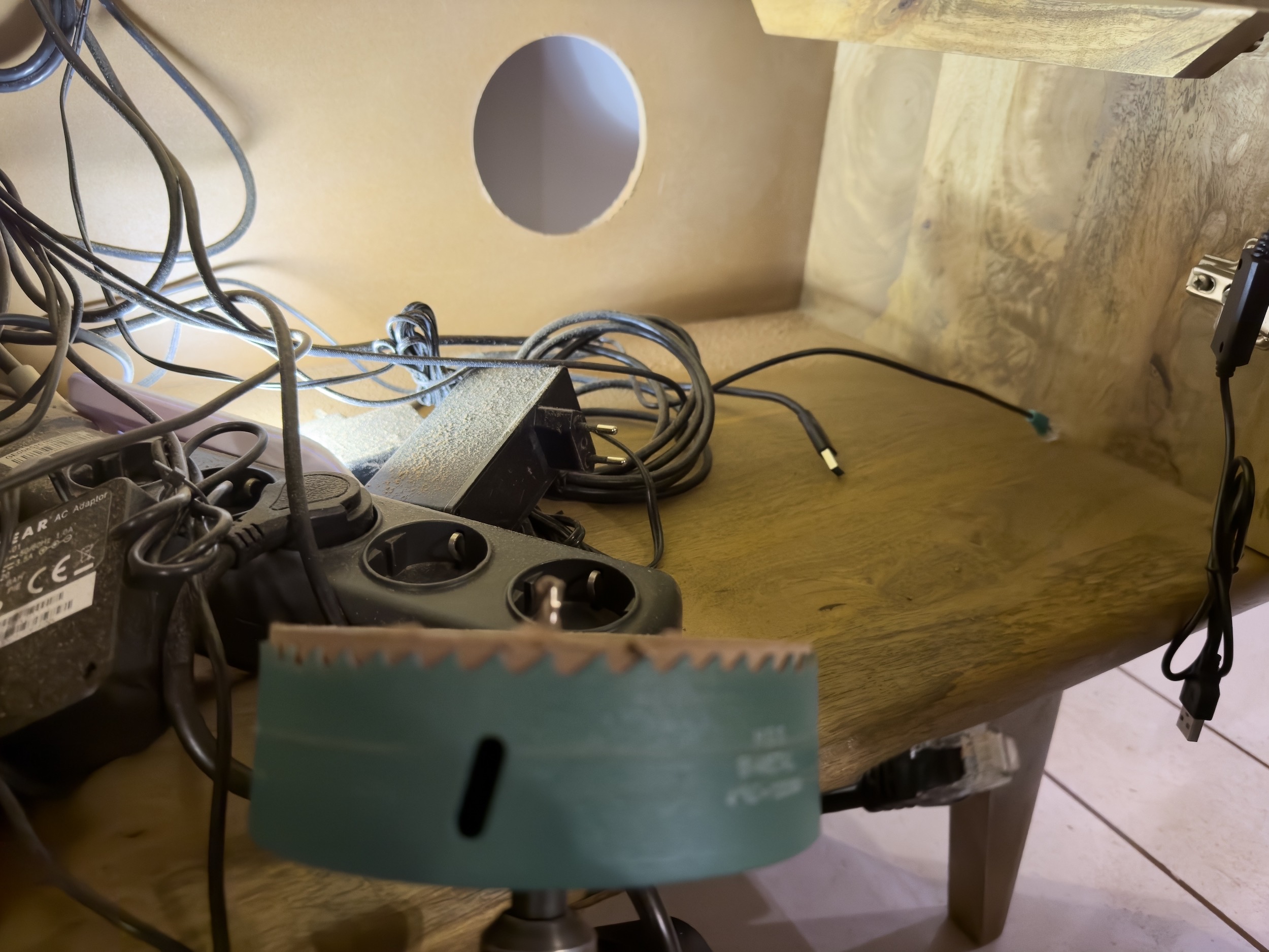
Then I stuck four pieces of soft material (bi-adhesive pad) to the fans, to have less vibration noise, four long self-tapping screws and the fans are attached inside.
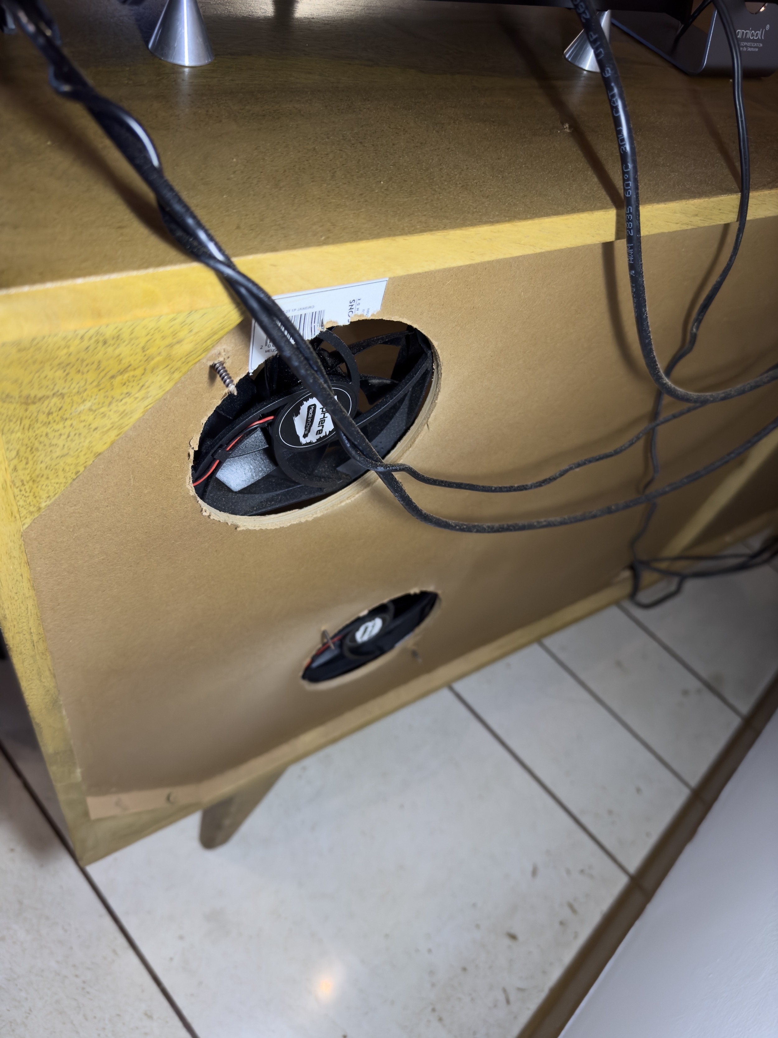
At the beginning I installed the upper fan without the grill, but after I realized that is better to use the grill before reinstall the stuff inside :)
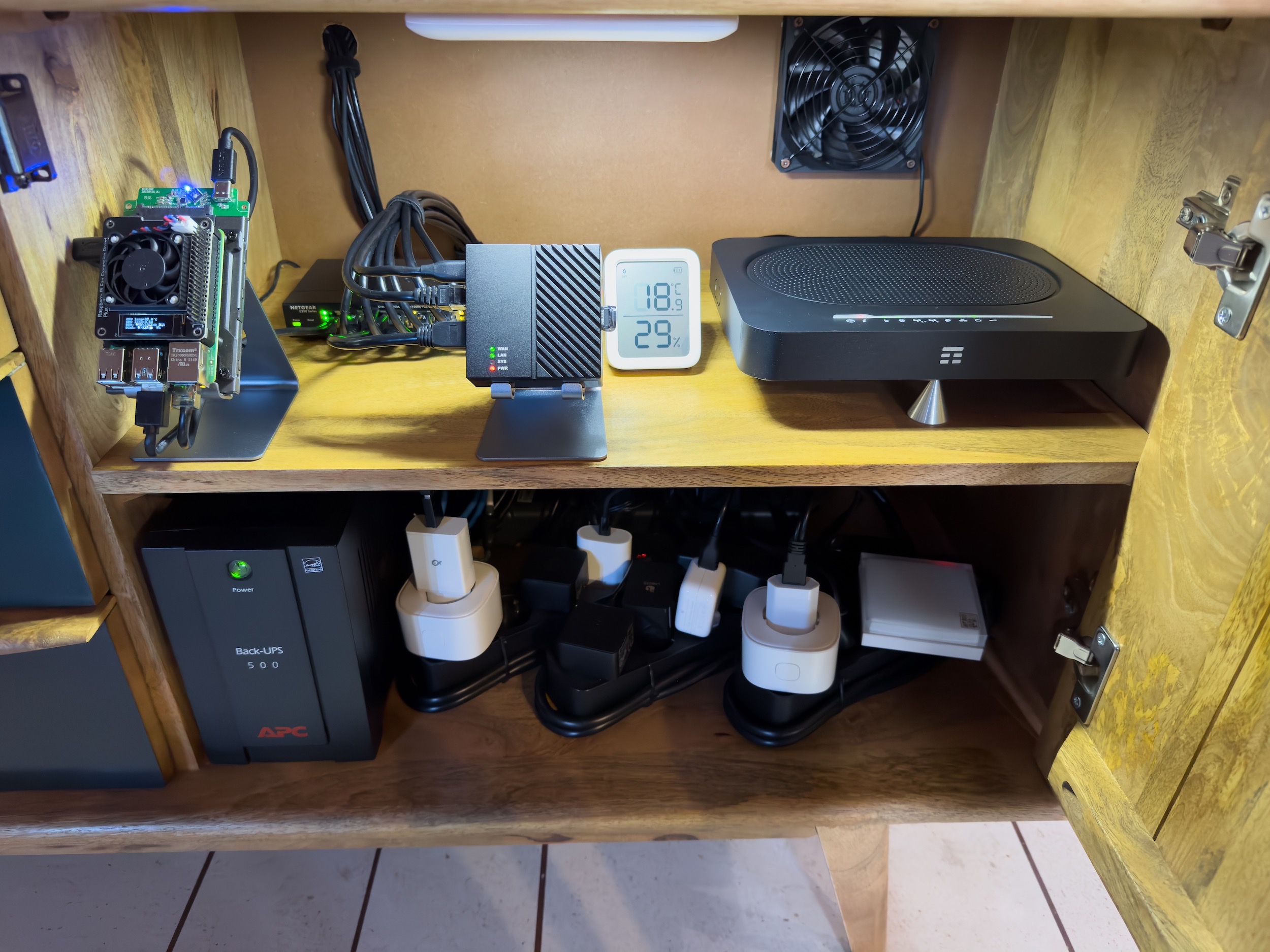
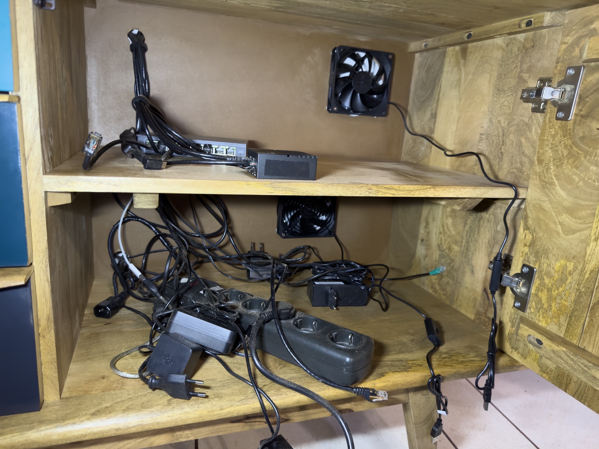
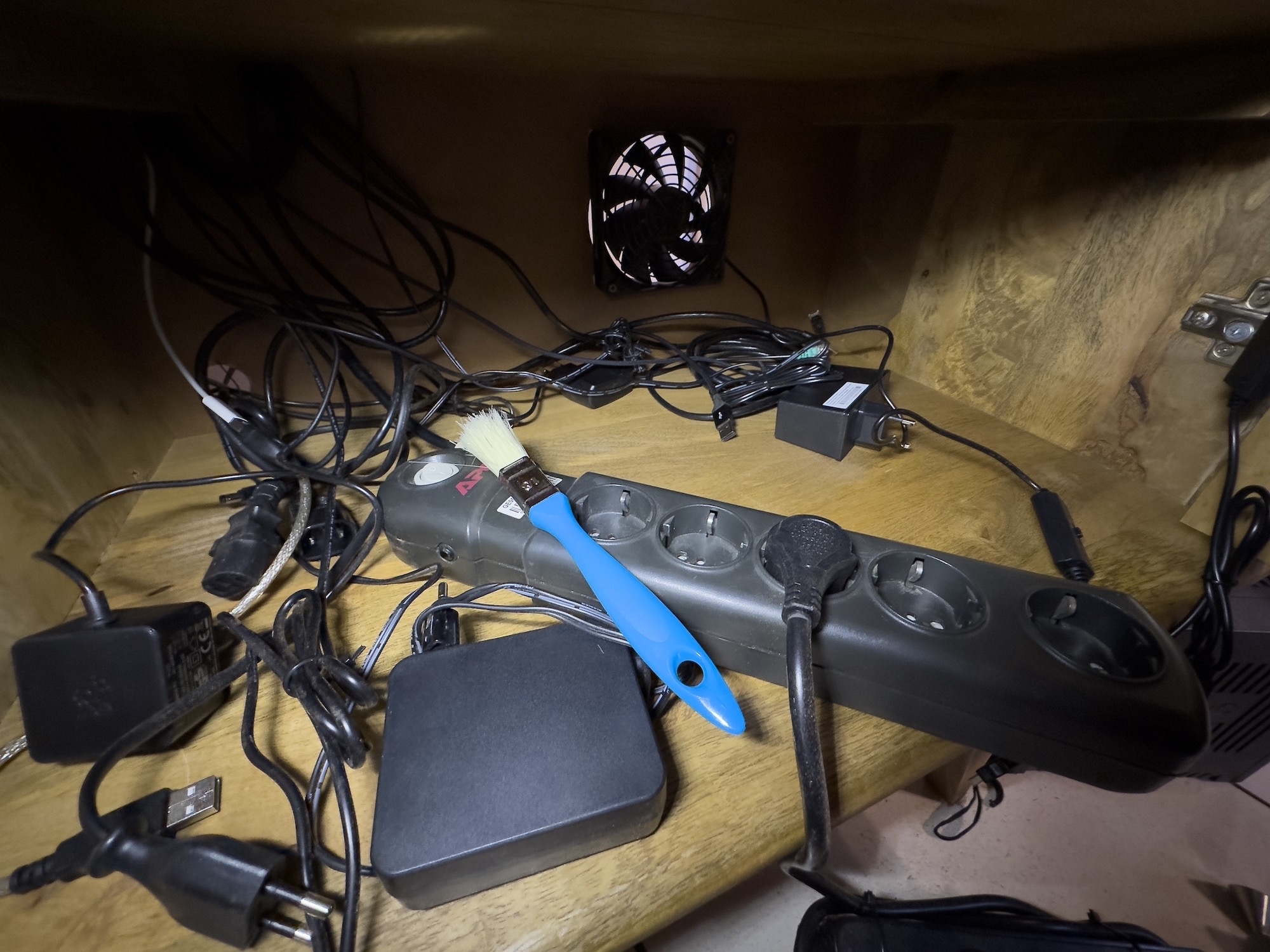
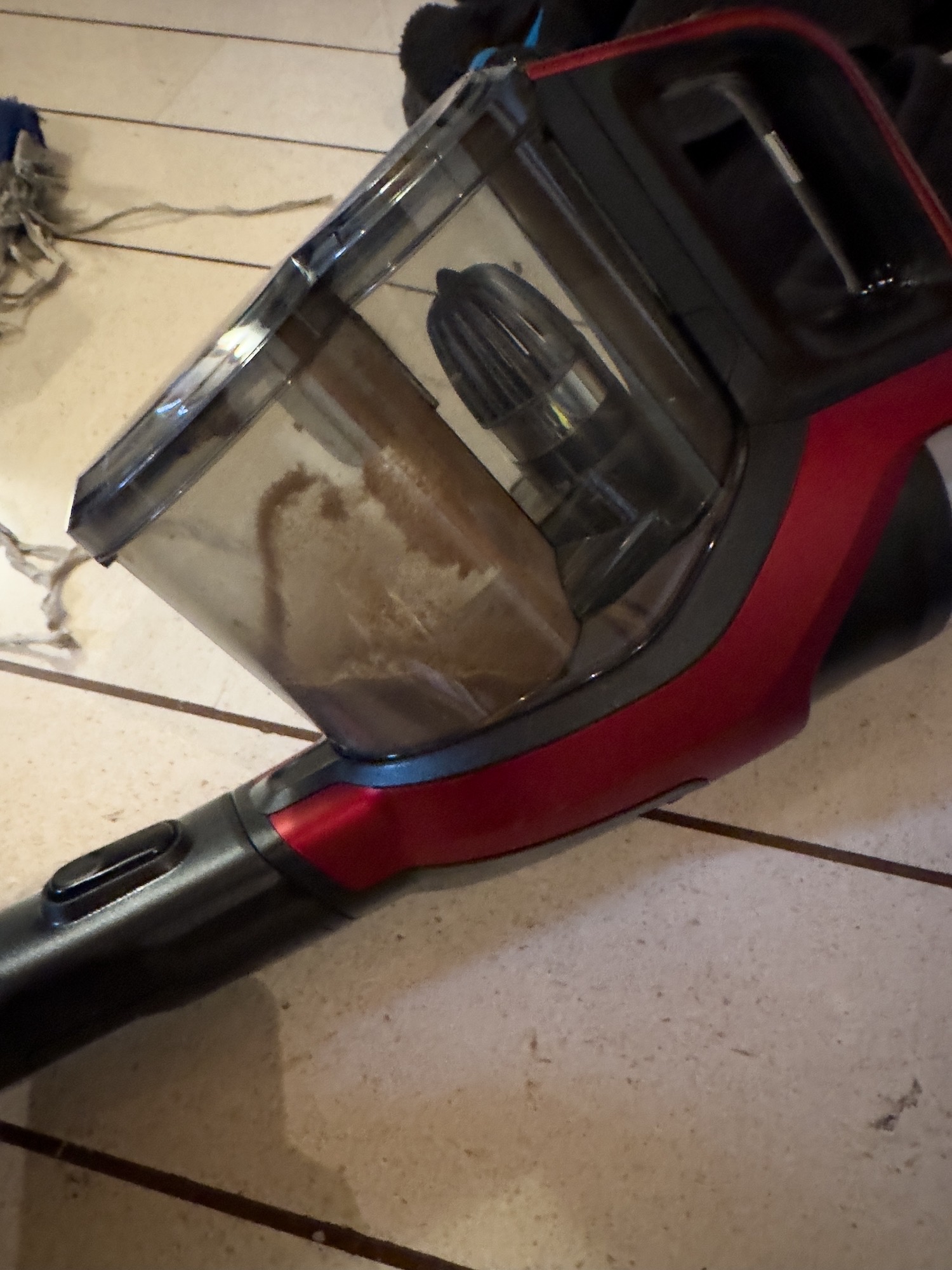
Then I cleaned up from the dust everything, using the vacuum and a brush
Last step was tidy up all the cables to optimize the mess/airflow
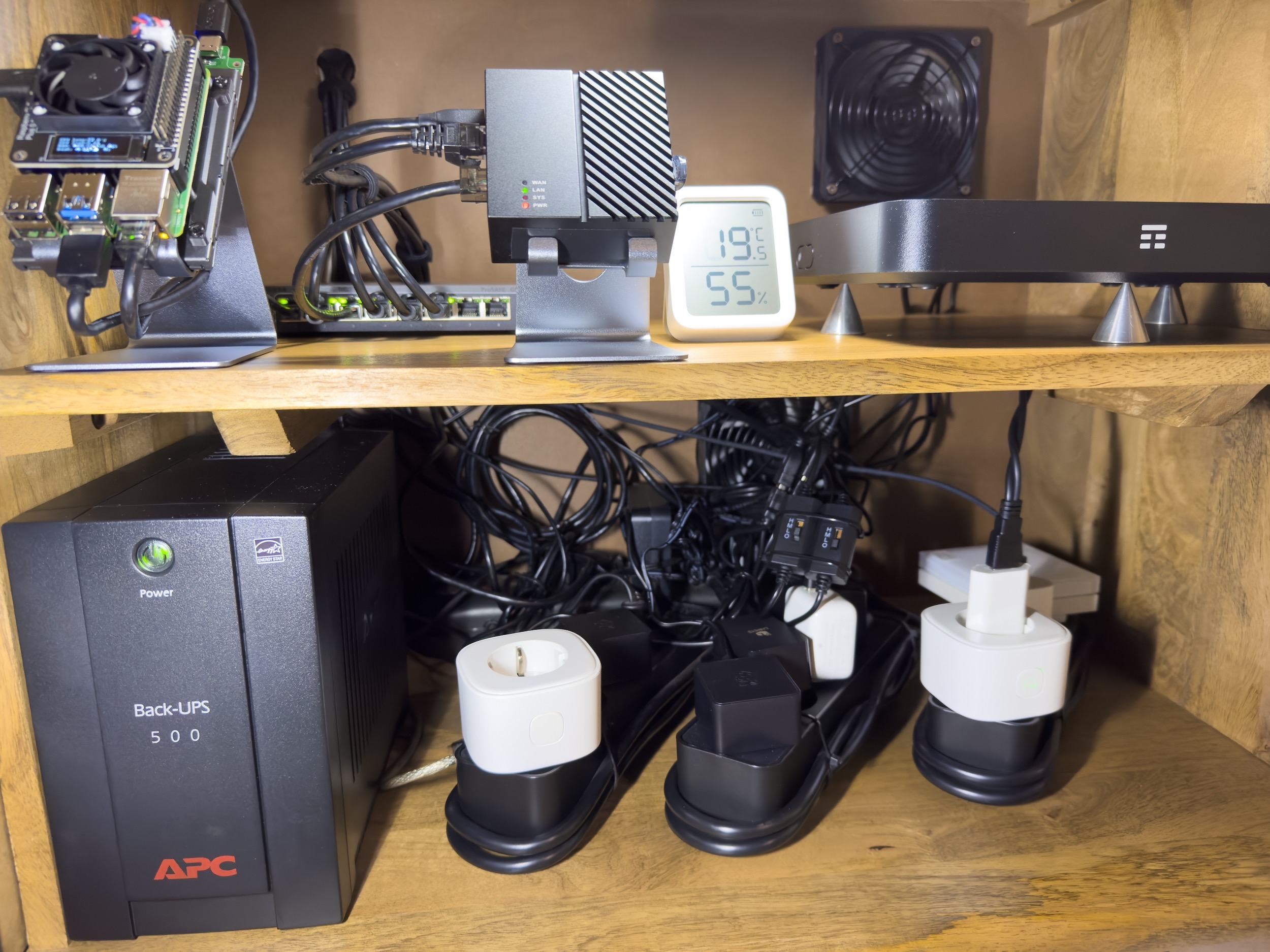
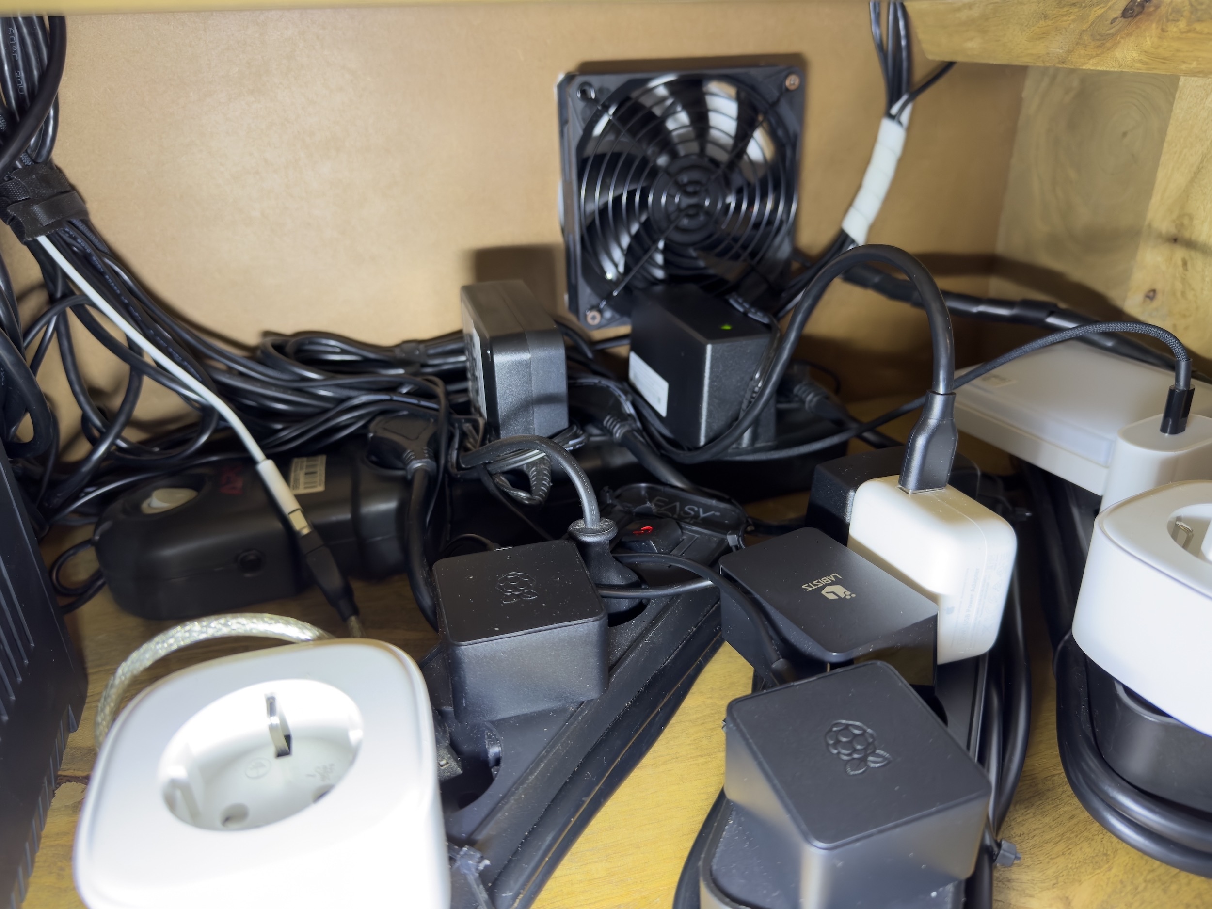
The fans work pretty well, maybe also “too much” because when I turn both on (at the lowest speed) the temperature of the inside hardware drops very fast, maybe I will not need to turn on both the fans but only the one above.
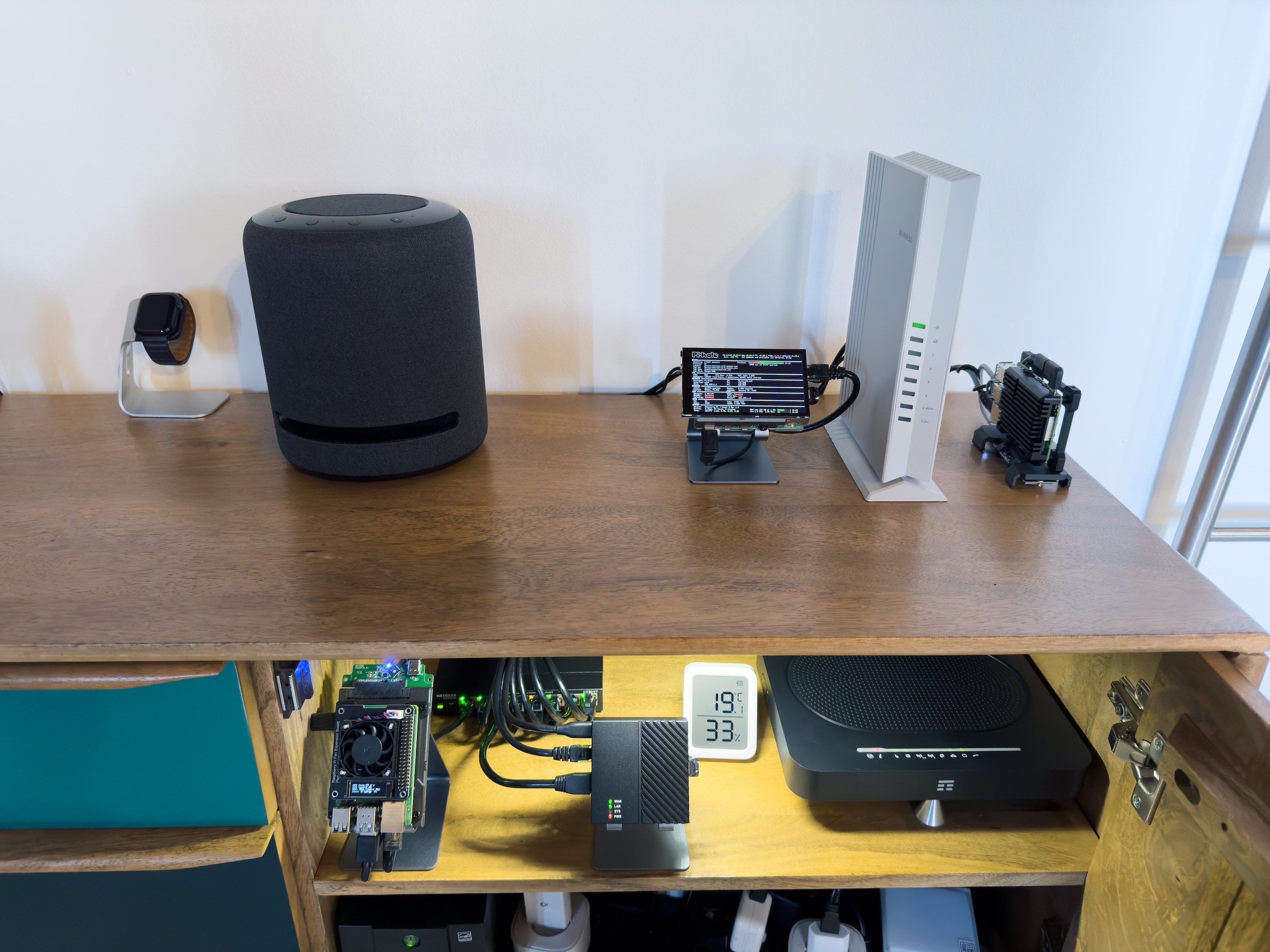
When I turn on the fans:
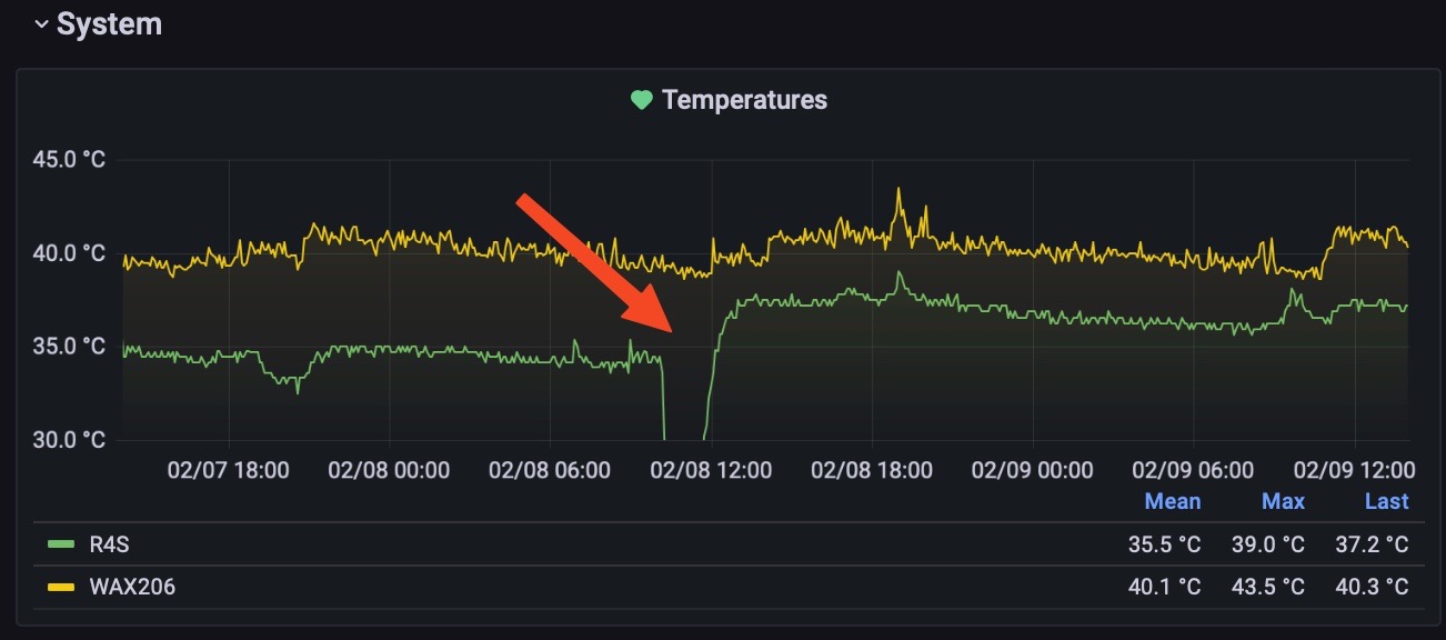
Anyway the fans will turn on/off automatically using HomeKit, something like “on above 30°, off below 25°”. During the summer inside the cabinet the temperatures rise very fast.
Netgear AX/6 AP
Previously (summer 2022) I bought a Netgear WAX202 that was -officially- supported by OpenWrt, but when I tested it I had been disappointed because the performance of the wifi 6, just behind a wall, was lower than wifi 5 of the R7800. So I returned it to Amazon and I decided to keep the R7800.
No, after some months, I decided to test again the progress with Wi-Fi AX, so I bought a Netgear WAX206 (specs) that should be a little more powerful than the WAX202. But with my surprise, I found that it’s more than “a bit” faster than the WAX202. It’s way better.
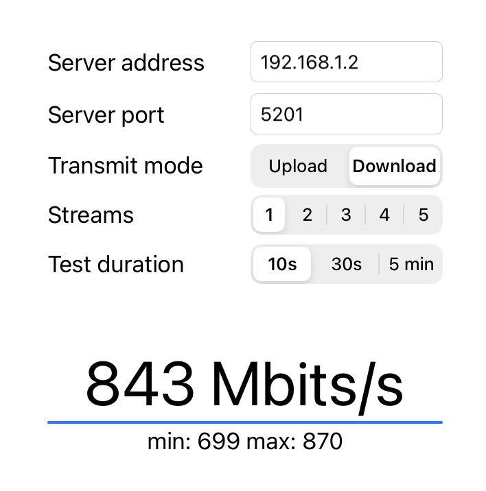
To be honest I bought also a Netgear EAX80, that is/should be the most powerful device of the trio, but since it has a Broadcom antennas, it will never be supported by OpenWrt. Anyway I bought these two APs to test if the EAX80 is faster and better than the WAX206 I would have kept it, also without OpenWrt because is nicer also. But instead I found that it has the same speed with my devices, for example the iPhone 14 Pro has only a 2x2 80MHz antenna, and can reach a theoretical speed of 866Mbps, and is the same for my other devices. So with these devices I can already fill the bandwidth without being able to take advantage of the other bandwidth from the EAX80:
With the EAX80 the speed was the same (or maybe little lower) but with the downside that I wasn’t unable to install OpenWrt and to build the Grafana wireless dashboards, and the web interface/management of the EAX80 is worse than the WAX206 Netgear default interface, indeed I was really surprised of how bad and without any settings the WebUI was. There are no ways to have more than 2 SSID, no way to have a different name on 2 different SSID, even no way to see how many clients are connected to an antenna. Instead the WAX206 “can be flashed” with OpenWrt and it also has a 2.5Gb WAN port that can be used inside the LAN when it’s working as AP only.
End of the short story: I decided to keep the WAX206 and send back the EAX80, although I love the EAX80 sleek design and nice grill/LEDs.
Then I had to create my own image of OpenWrt for the WAX206. I had to do this because the WAX206 is still -officially- unsupported (also in the Master/Snapshot branch), but there’s the kernel support using this repository. But this story goes on in the software section of this post.
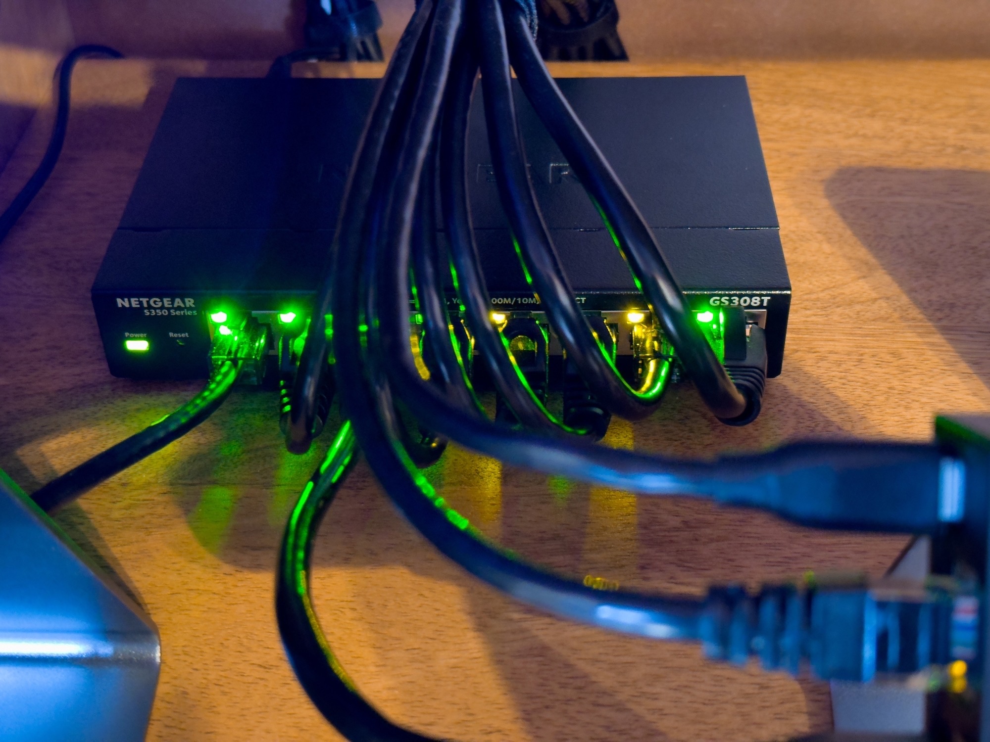
Netgear GS308T switch
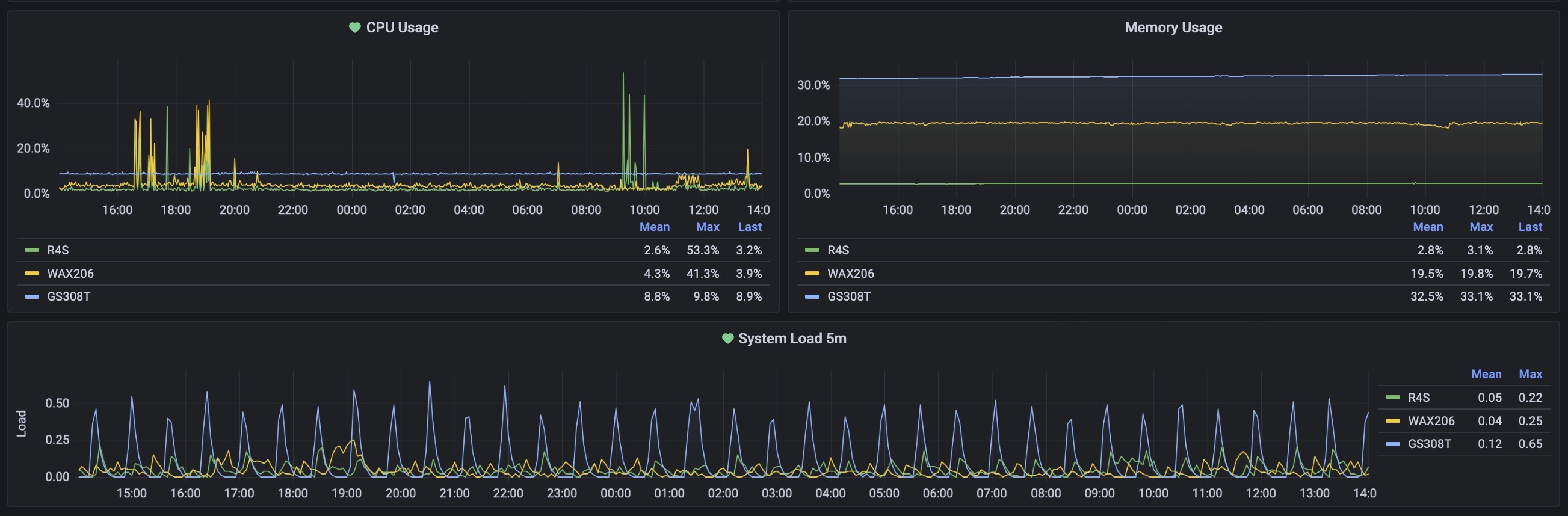
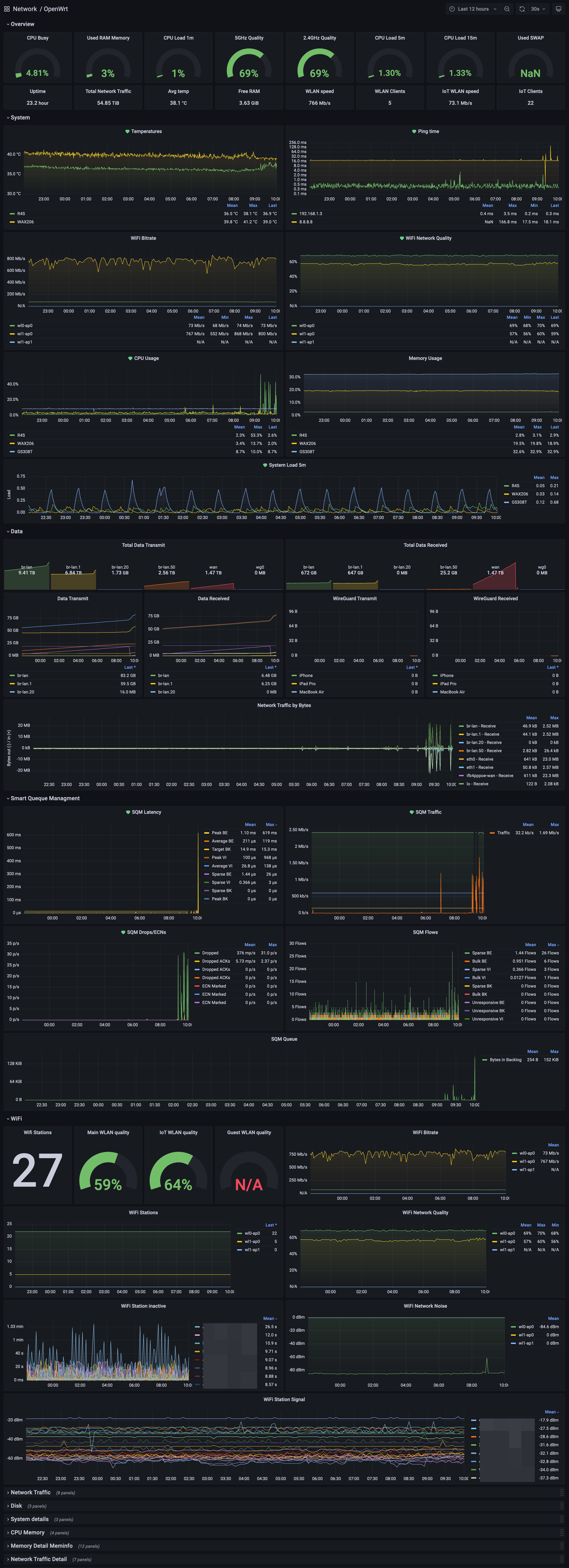
I also bought a switch that is supported by OpenWrt, just because using OpenWrt I can export also the metrics from it and so, build a full Grafana Dashboard with all the info from my network devices. But I’ll talk more about this in the “software-Grafana” section, just a sneak peek of the switch and graphs:
Wiring
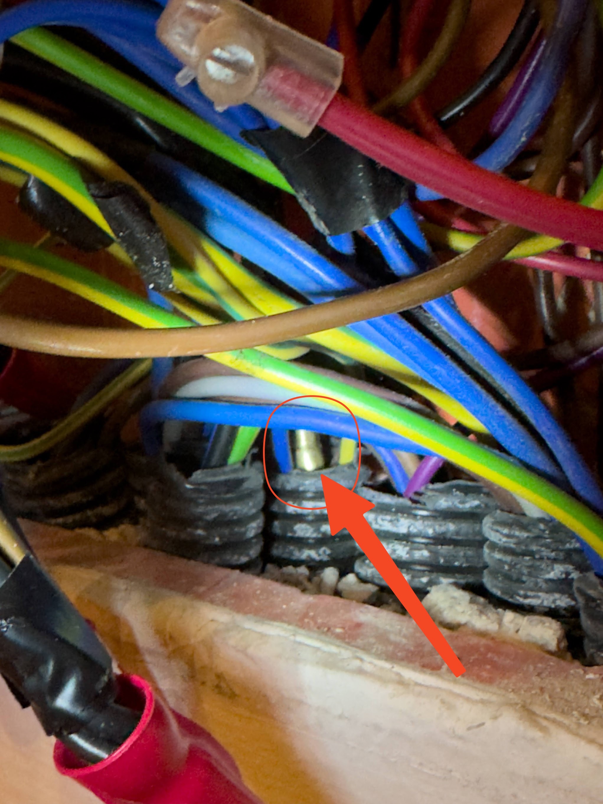
I don’t have much to write about the wiring stuff, it’s a pretty common and easy procedure. I have simply bought a probe used by electricals, 30 meters of Ethernet 6a FTP cable, and with a good deal of patience I found the path inside the walls and then I put in the cables.
This is the patience that I had…spot the probe in this mess:
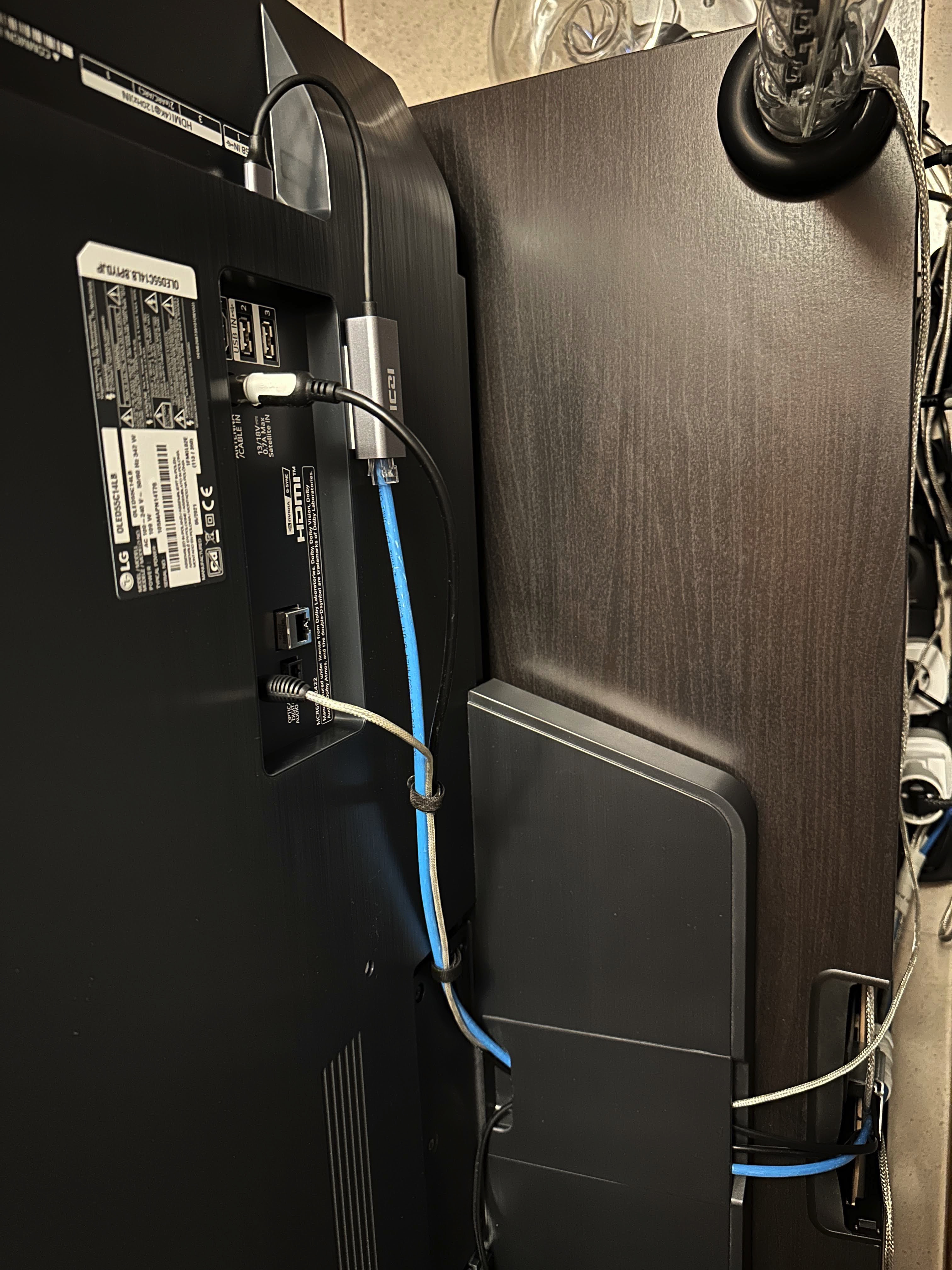
I had also a bad surprise with my 2021 LG OLED 55C1 television because I discovered that it has only the 100mbps Ethernet port. I noticed this because the 1000mbps LED of the switch was inactive. So I searched and I discovered that almost all the /current/ TV are still using 100mbps port (yes in 2021). Well, 100mbps are more than sufficient for a 4k streaming video nowadays, and I need the wired connection only to use the TV with HomeKit without lag or Wake On LAN issues, but this 100mbps port is definitely too old and it’s absurd that manufacturers still use it, but eventually, they will have to find an argument for us to buy a new model?
Anyway, using a cable connected to the TV, now when I rise/lower the volume from Home app, it acts without any lag. Also the Wake On Lan works flawless.
Tip: you can also have some more bandwidth using a USB 3 to Ethernet adapter (for 10-12€), using it the TV can reach about 300mbps.
Software
Talking about the software improvement, I made some important changes for security and performance: I configured the network using VLANs instead of subnets and I compiled some custom OpenWrt images for my hardware (nanoPi R4S, Netgear WAX206 and GS308T).
VLANs and HomeKit
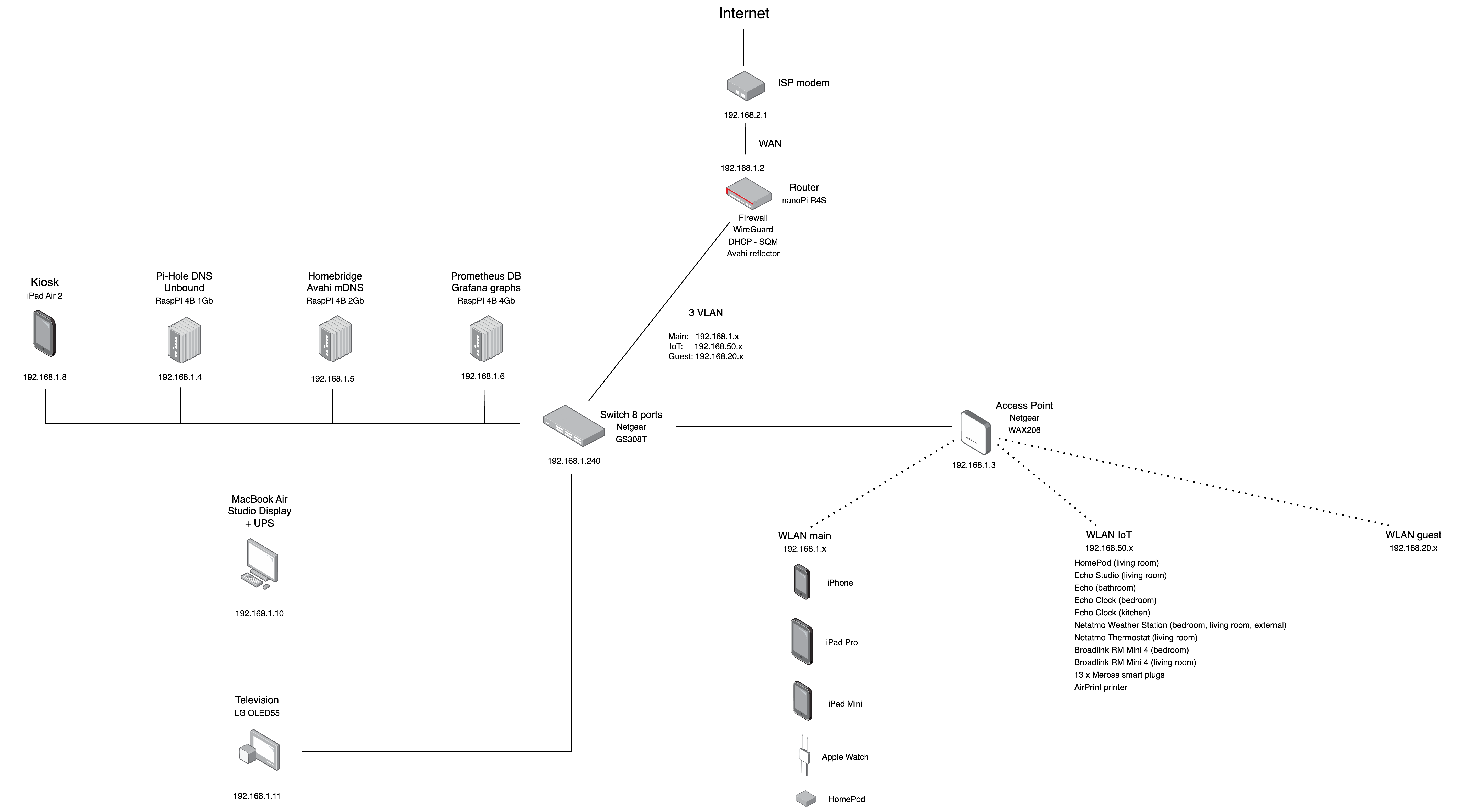
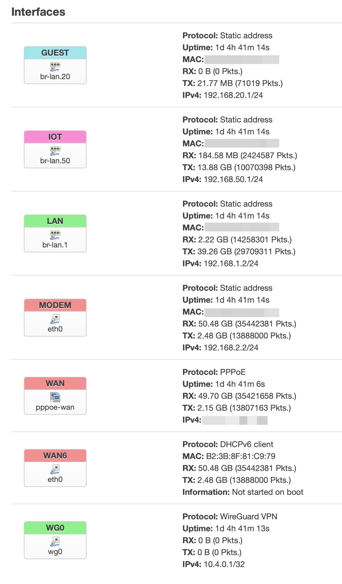
Also if this setup can be obtained with only subnets (because they are all assigned to wireless interfaces) I decided to switch all the networks from 3 separated subnets to 3 separated vlans. First I want to show my network config now:
The bigger (and only?) issue was with Apple Home/HomeKit configuration, because as soon as I put the Homekit devices in a IoT separated VLAN from your iPhone, Mac, etc.. the devices stopped to respond. This happens because Apple is using its mDNS advertiser (Bonjour), and the queries made by the HomeKit server (in my case the Homebridge server on 192.168.1.x lan) in another vlan, can’t be discovered by the devices in another VLAN.
To fix this I had to install “something” on the router that can reflect the queries from a lan, to another (v)lan. And this “something” is called Avahi:
an mDNS/DNS-SD daemon implements Apple’s Zeroconf architecture (also known as “Rendezvous” or “Bonjour”)
That has the option to reflect the queries from the Homebridge lan to another lan, this option is called indeed reflector. So I installed Avahi on my router and then I modified just two parameters in /etc/avahi/avahi-daemon.conf
Under the [server] section I added my IoT VLAN only (by default it reflects on all the interfaces, that is less safe)
allow-interfaces=br-lan.1,br-lan.50
And under the [reflector], I changed from no to yes
enable-reflector=yes
then I just reloaded it with service avahi-daemon restart (and be sure to also reload the Homebridge service with sudo hb-service restart).
Solved this, in order to have the DHCP, mDNS and DNS addresses sent from the router to the IoT vlan, I also added some rules to the firewall:
config forwarding
	option src 'lan'
	option dest 'iot'

config forwarding
	option src 'iot'
	option dest 'WAN'

config rule
	option name 'IoT DHCP'
	list proto 'udp'
	option src 'iot'
	option dest_port '67-68'
	option target 'ACCEPT'

config rule
	option name 'IoT DNS'
	option src 'iot'
	option dest_port '53'
	option target 'ACCEPT'

config rule
	option name 'IoT mDNS'
	list proto 'udp'
	option src 'iot'
	list dest_IP '224.0.0.251'
	option dest_port '5353'
	option target 'ACCEPT'

config rule
	option src 'iot'
	list dest_ip '192.168.2.0/24'
	option target 'DROP'
	option name 'IoT Modem'
	list proto 'all'
	option dest 'wan'
Now the devices inside the IoT vlan are isolated from the other devices in othe (v)lans and they don’t have access to the router, modem or other devices. This is an improvement for security and privacy.
The same can be configured for the guest vlan, except for the Avahi mDNS reflector that is not needed obviously, you just have to allow the guests devices to browse the web, have access to DNS and DHCP.
Access Point
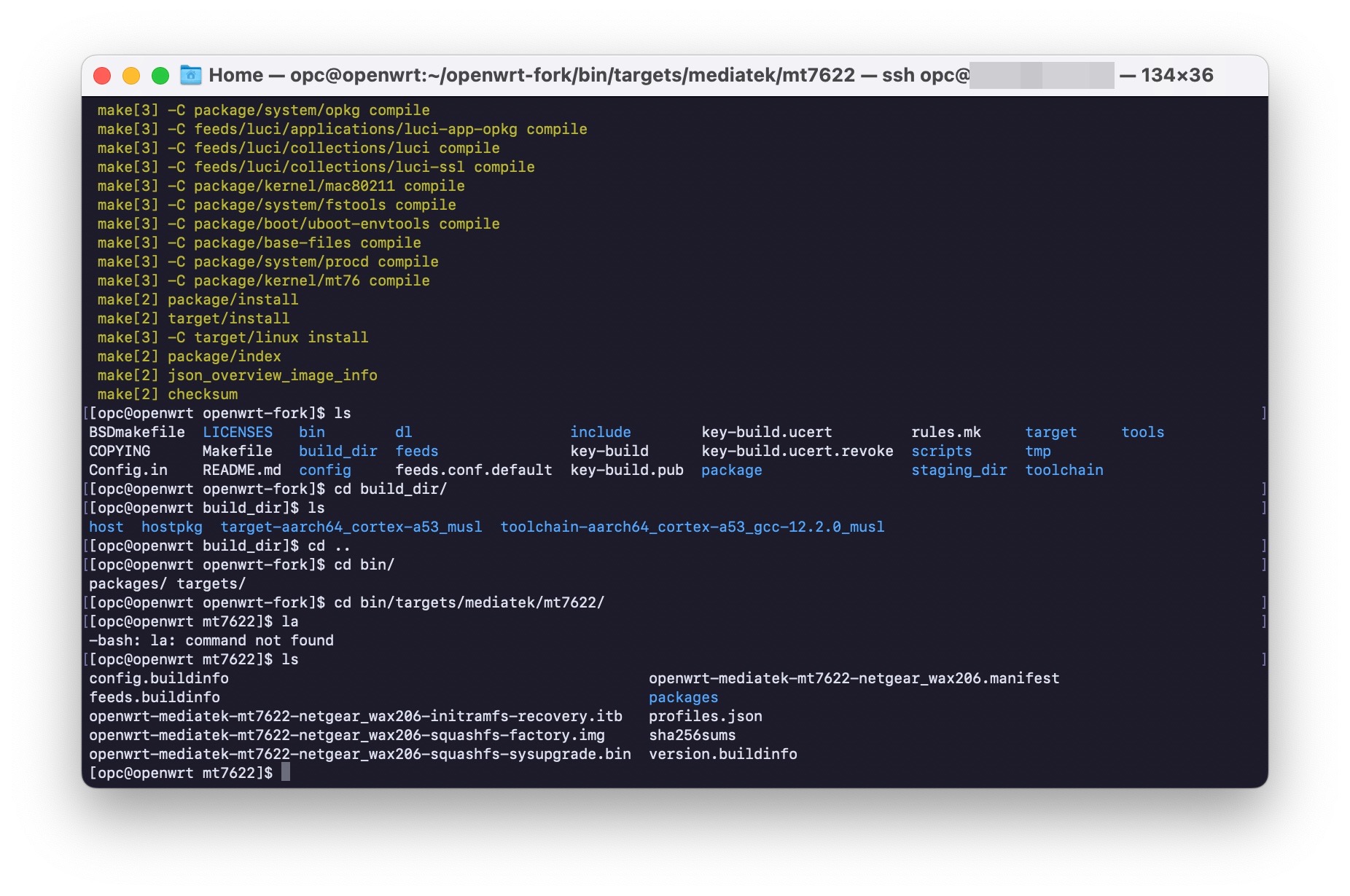
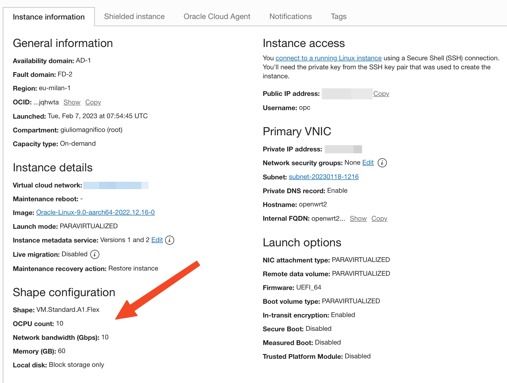
Since the WAX206 is not officialy supported by OpenWrt (also in the master branch), I had to compile my OpenWrt image. And I did this using an Oracle Cloud istance, because I was surprised how on a “forever free plan” you can have access to a quite powerful ARM virtual machine. This hardware results in a full build in about 35/40 minutes without use your local machine or electricity. This Oracle free tier is now my new OpenWrt build machine, and I made also my custom builds for the nanoPi R4S router and Netgear GS308T switch.
And with my surprise, in the latest image, the power LED is now green (instead of orange), and this is a bit nicer than the ugly orange one before. Kudos to the dev who changed it.
Talking about the configuration on it, now it is operating as Access Point only, without firewall, DNS, DHCP or other stuff, all is demanded to the nanoPi R4S.
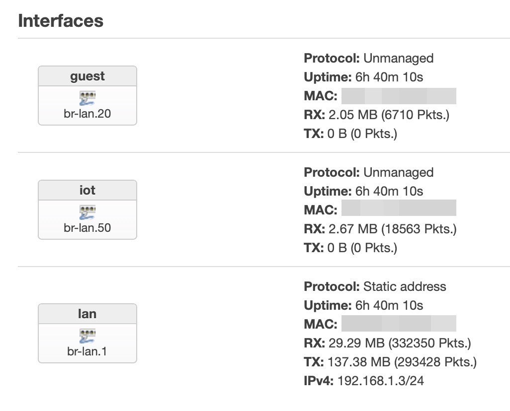
On the WAX206 I had only to create 3 VLAN, two tagged and without any IP or DHCP or firewall, and one, the VLAN that I use to connect to the access point, untagged and with only a static IP (192.168.1.3).
config bridge-vlan
	option device 'br-lan'
	option vlan '1'
	list ports 'lan4'

config bridge-vlan
	option device 'br-lan'
	option vlan '10'
	list ports 'lan4:t'

config bridge-vlan
	option device 'br-lan'
	option vlan '20'
	list ports 'lan4:t'

config bridge-vlan
	option device 'br-lan'
	option vlan '50'
	list ports 'lan4:t'

config interface 'lan'
	option proto 'static'
	option device 'br-lan.1'
	option ipaddr '192.168.1.3'
	option netmask '255.255.255.0'
	option gateway '192.168.1.2'
	list dns '192.168.1.4'

config interface 'iot'
	option device 'br-lan.50'
	option proto 'none'

config interface 'guest'
	option device 'br-lan.20'
	option proto 'none'

config device
	option name 'br-lan.1'
	option type '8021q'
	option ifname 'br-lan'
	option vid '1'
	option ipv6 '0'

config device
	option name 'br-lan.10'
	option type '8021q'
	option ifname 'br-lan'
	option vid '10'
	option ipv6 '0'

config device
	option name 'br-lan.20'
	option type '8021q'
	option ifname 'br-lan'
	option vid '20'
	option ipv6 '0'

config device
	option name 'br-lan.50'
	option type '8021q'
	option ifname 'br-lan'
	option vid '50'
	option ipv6 '0'
This to be able to access to the AP from the main lan (br-lan.1) but to avoid that a device in the IoT or Guest network sets its own IP as the IP of the AP and indeed, doing this it would be able to bypass the firewall an be inside my main lan.
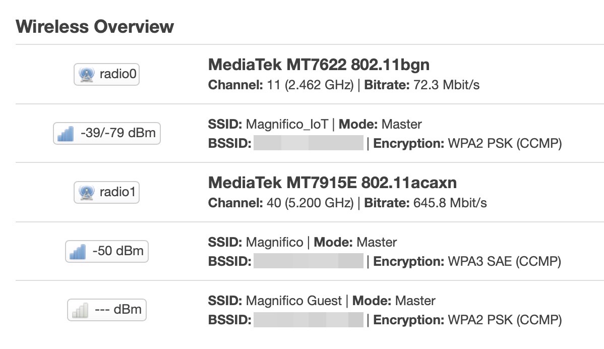
Then I assigned the correct wireless interfaces to the respective network interfaces/VLANs and that’s all.
I also noticed that this setup is a bit faster because the WAX206/AP is totally transparent and is doing nothing (except their wireless things), and all is demanded to the R4S that is way more powerful and all is routed straight inside it and by it. The gain is marginal, from 0,6/0,7ms to 0,4/0,5ms.
Router
On the nanoPi R4S I’ve made the same VLANs obviously, then I created the same network interfaces and I assigned to every new network its own firewall zone and every network interface has also the DHCP and DNS assigned.
config interface 'lan'
	option device 'br-lan.1'
	option proto 'static'
	option ipaddr '192.168.1.2'
	option netmask '255.255.255.0'
	list dns '192.168.1.4'

config bridge-vlan
	option device 'br-lan'
	option vlan '1'
	list ports 'eth1'

config bridge-vlan
	option device 'br-lan'
	option vlan '10'
	list ports 'eth1:t'

config bridge-vlan
	option device 'br-lan'
	option vlan '20'
	list ports 'eth1:t'

config bridge-vlan
	option device 'br-lan'
	option vlan '50'
	list ports 'eth1:t'

config interface 'guest'
	option proto 'static'
	option device 'br-lan.20'
	option ipaddr '192.168.20.1'
	option netmask '255.255.255.0'
	list DNS '192.168.1.4'
	option gateway '192.168.1.2'

config interface 'iot'
	option proto 'static'
	option device 'br-lan.50'
	option ipaddr '192.168.50.1'
	option netmask '255.255.255.0'
	list dns '192.168.1.4'

config device
	option name 'br-lan.10'
	option type '8021q'

config device
	option name 'br-lan.20'
	option type '8021q'
	option ifname 'br-lan'
	option vid '20'
	option ipv6 '0'
	option acceptlocal '1'

config device
	option name 'br-lan.1'
	option type '8021q'
	option ifname 'br-lan'
	option vid '1'
	option ipv6 '0'
	option acceptlocal '1'

config device
	option name 'br-lan.50'
	option type '8021q'
	option ifname 'br-lan'
	option vid '50'
	option acceptlocal '1'
	option ipv6 '0'
Switch
The last thing is to tell the switch which physical port is must be assigned to which VLAN and if it must be tagged or untagged.
In my case, all the 8 ports of the switch are assigned to the br-lan.1 (the main lan) untagged, and the ports 3 and 4 are tagged and assigned to the IoT and Guest VLANs. Because to the port 4 of the switch is connected the AP with the same VLANs.
config bridge-vlan 'lan_vlan'
	option device 'switch'
	option vlan '1'
	list ports 'lan1'
	list ports 'lan2'
	list ports 'lan3'
	list ports 'lan4'
	list ports 'lan5'
	list ports 'lan6'
	list ports 'lan7'
	list ports 'lan8'

config device
	option name 'switch.1'
	option macaddr ''

config interface 'lan'
	option device 'switch.1'
	option proto 'static'
	option netmask '255.255.255.0'
	option ip6assign '0'
	list dns '192.168.1.4'
	option gateway '192.168.1.2'
	option ipaddr '192.168.1.240'

config bridge-vlan
	option device 'switch'
	option vlan '10'
	list ports 'lan3:t'
	list ports 'lan4:t'

config bridge-vlan
	option device 'switch'
	list ports 'lan3:t'
	list ports 'lan4:t'
	option vlan '20'

config bridge-vlan
	option device 'switch'
	option vlan '50'
	list ports 'lan3:t'
	list ports 'lan4:t'

config device
	option name 'switch.10'
	option type '8021q'
	option ifname 'switch'
	option vid '10'

config device
	option name 'switch.20'
	option type '8021q'
	option ifname 'switch'
	option vid '20'

config device
	option name 'switch.50'
	option type '8021q'
	option ifname 'switch'
	option vid '50'
Grafana
For the Grafana setup, since now I have all the 3 hardware devices that can create their metrics, so I changed the layout of some panels in order to have all the devices displayed inside one panel. This is very useful because when I get the daily reports I can see the hardware status of all the devices in one.
But with the new setup that uses VLANs instead of subnet, the Prometheus exporters weren’t working, I tried to change the interface to br-lan.x but the only way I figured out to have the setup working, was to use an asterisk for the interfaces, that means “all the available interfaces”, that is also what I want:
/etc/config/prometheus-node-exporter-lua
config prometheus-node-exporter-lua 'main'
        option listen_interface '*'
        option listen_port '9100'
        option listen_ipv6 '0'
Conclusion
I spent lots of time, about 2 months, in this, but I think I reached a good setup for the summer and future updates of the network. Now the current speed of the wireless devices is the maxium they can reach with their antenna setup.
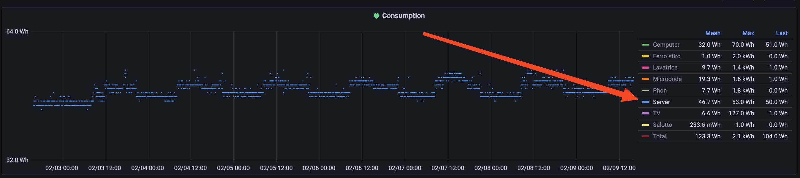
And about the consumpution, the whole setup uses about 45-50W, as you can see from the Grafana “home dashboard” of the last 7 days:
Feel free to ask or warn me, if you need more information, using the comments or sending me an email.